![]()
IN STOCK
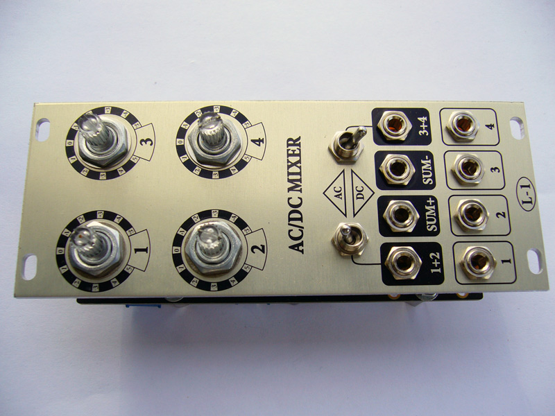
AC/DC Mixer for Eurorack - true syle! No wiring! Other formats and 15V - possible!
PCB - 2mm thickness, gold platted, black mask. $25
Two panels - 10HP front & back. Anodized alu, black print. $25
SMD parts + soldering. $10 (Who order SMD soldering please note if 15V version in payment comments, I make 12V by default)
Shipping per set: $5 - only board, $8 - board+panels.
TOTAL for complete set with shipping: $68
Paypal: aleksei1laman@gmail.com
Assembled module $260 + $10 shipping.
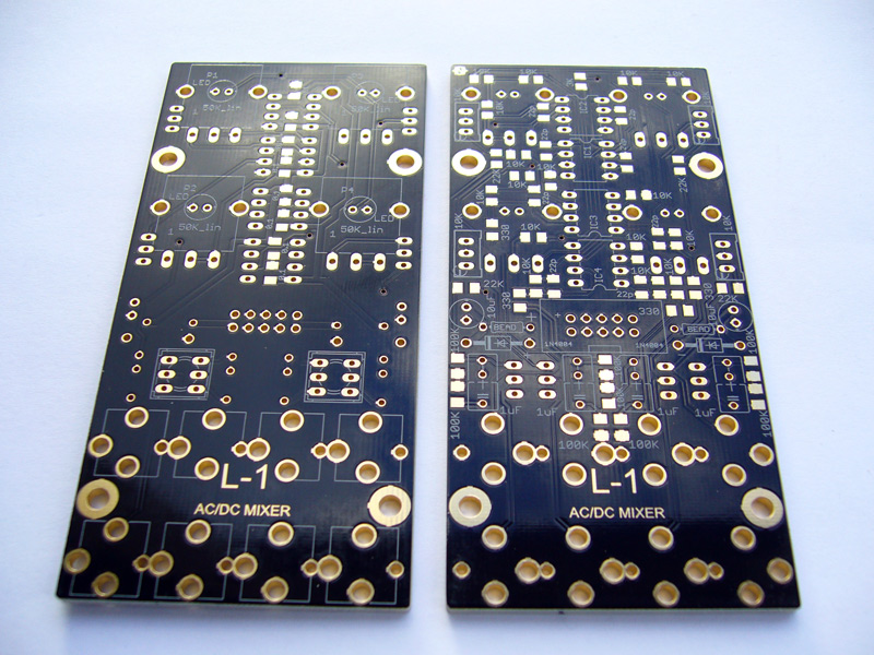
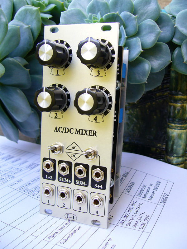
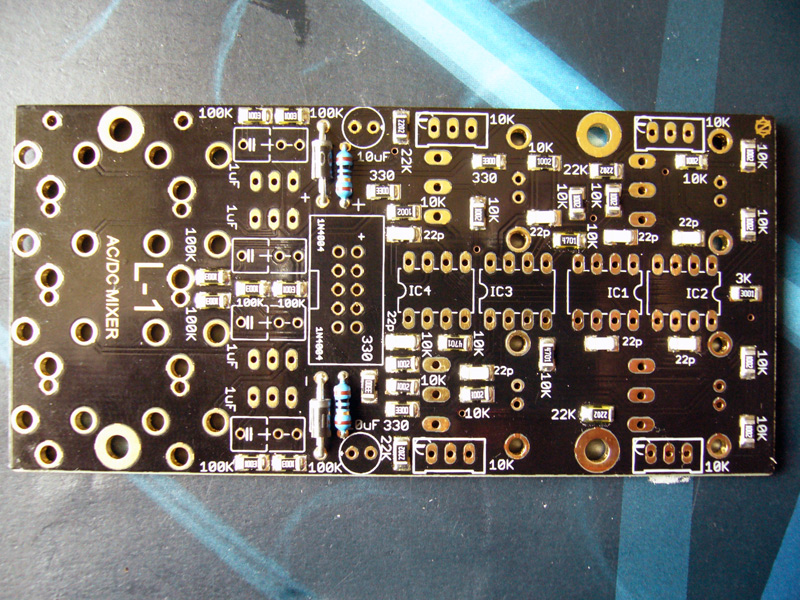
This is PCB and front & back panels for assembling Eurorack AC/DC Mixer.
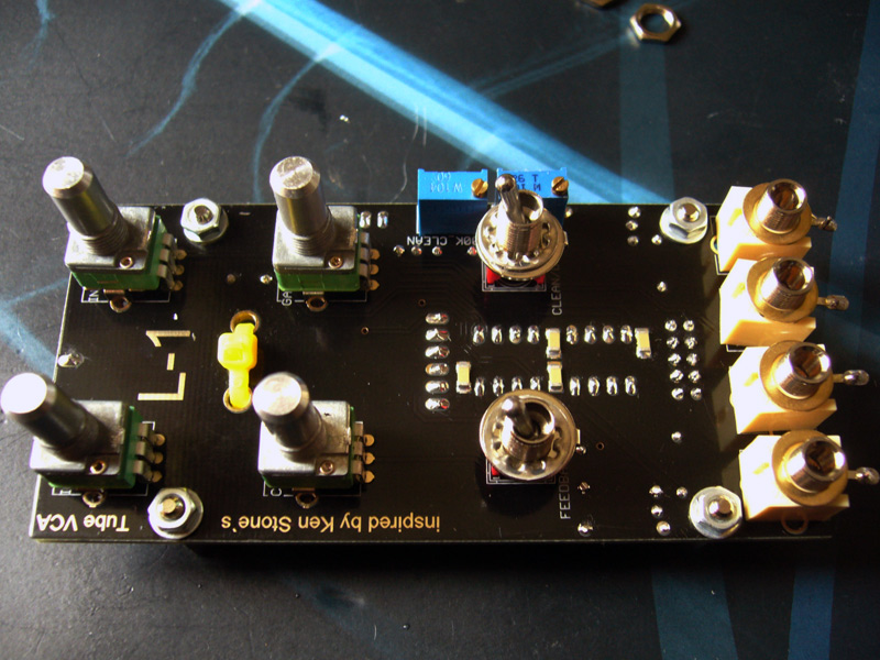
Mixer has 4 inputs which can be mixed in pairs and all together. Inputs are AC or DC coupled in pairs by switches. Potentiometers attenuate gain, unity gain at the center their range, max gain = 2. So it is amplifying mixer. PCB made for 15mm Alpha pots with clear shaft, so funny 3mm LEDs mounted. I've choose OP270 as summing amplifiers because of their great DC precision and sound quality.
Thread at MuffWiggler forum http://www.muffwiggler.com/forum/viewtopic.php?t=60398
The design is adapted for Eurorack format but 15V is possible without changes. Boards have mounting holes for M3 screws, footprints of potentiometers, switches and power connector are compatible with MTA100 headers. Jacks can be wired with shielded or other wires. So 5U-ers are welcome.
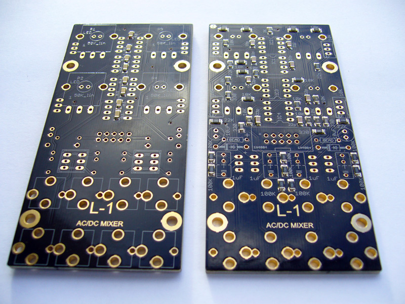
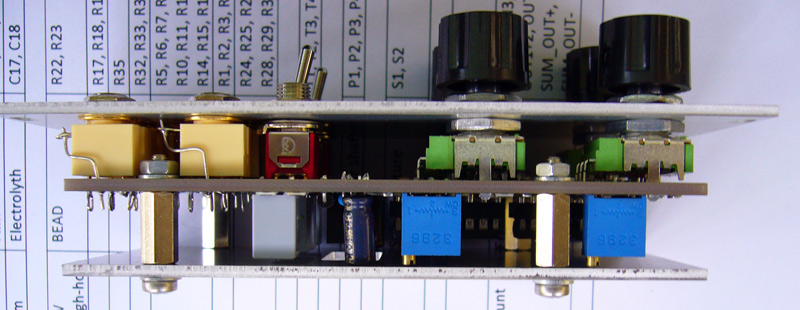
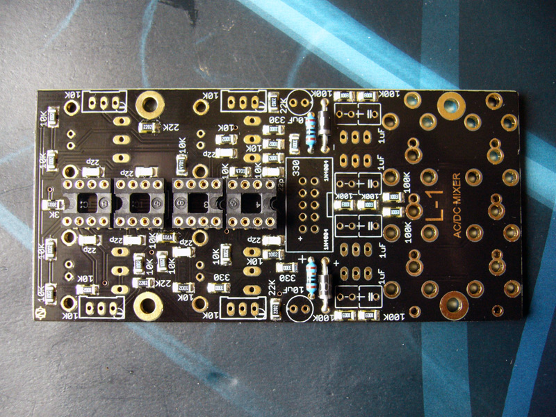
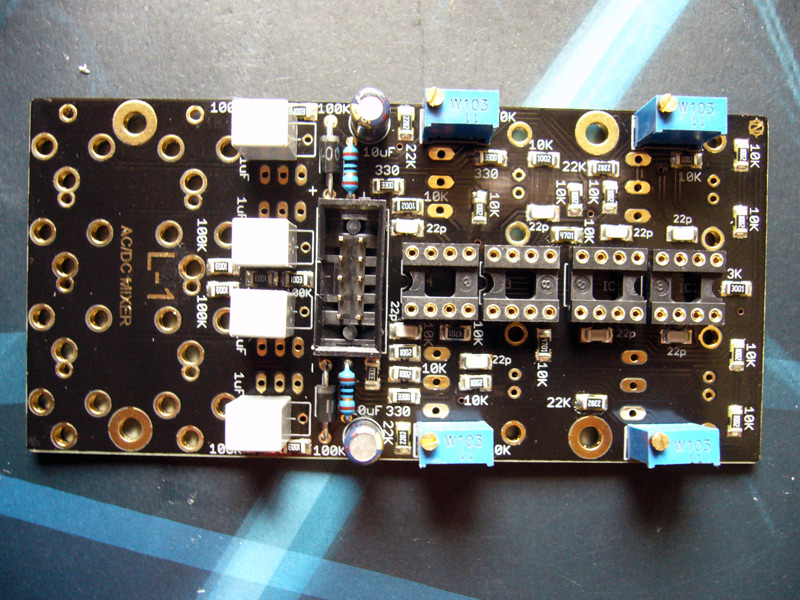
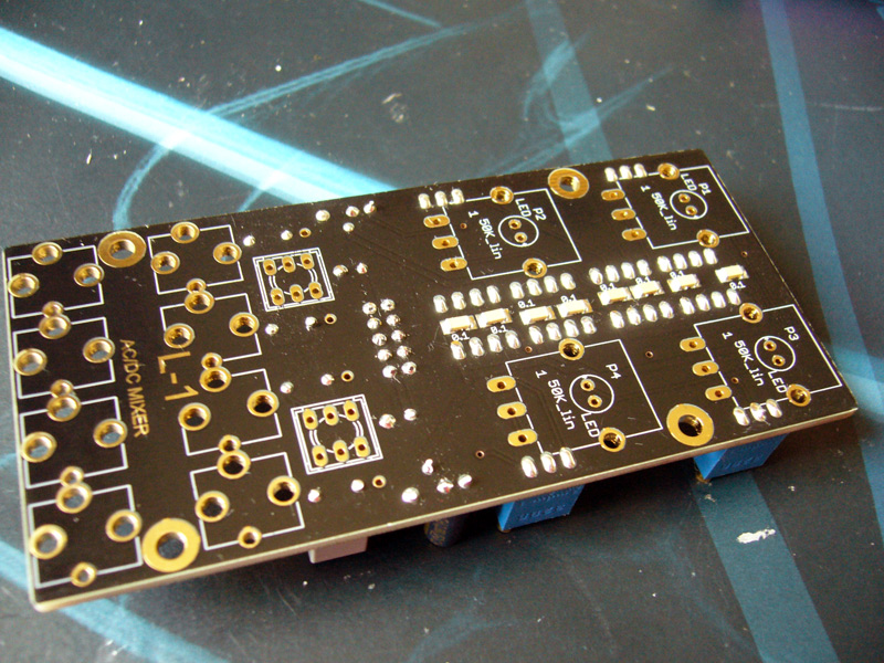
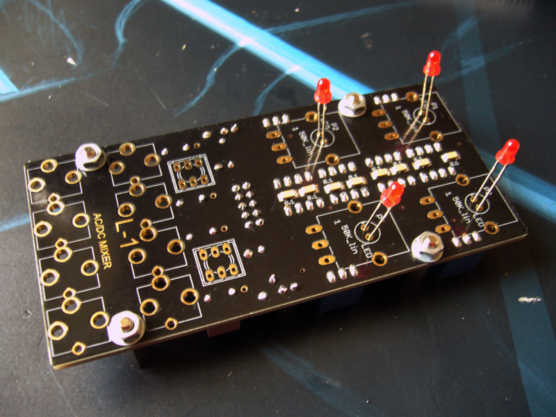
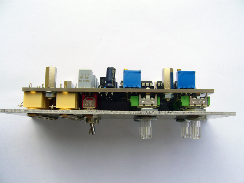
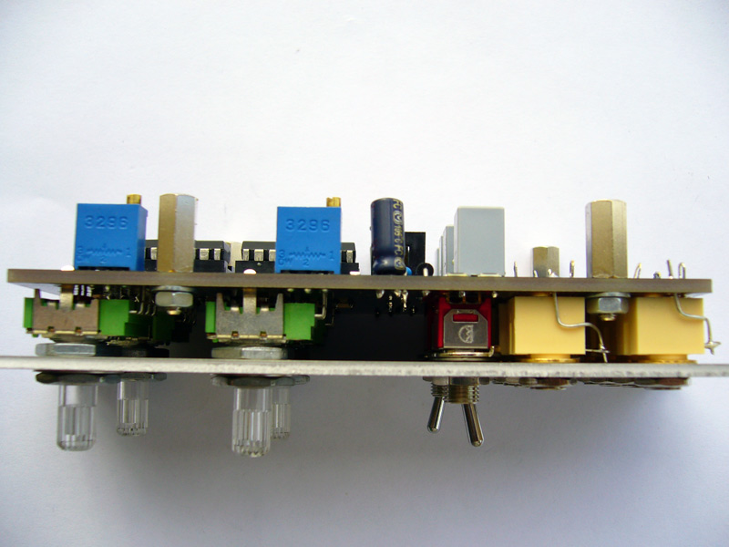
PCB from both sides:
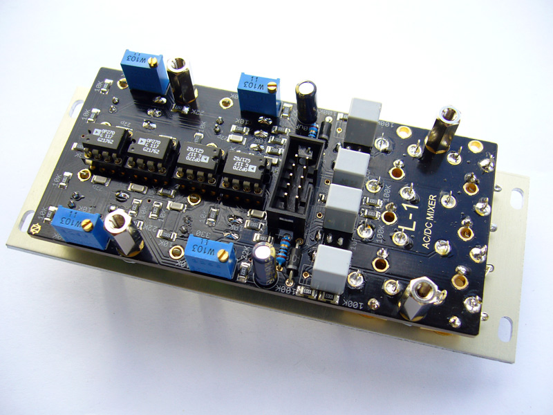
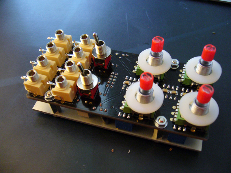
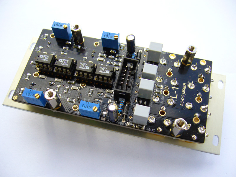
PCB with soldered SMD parts:
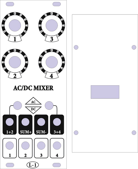
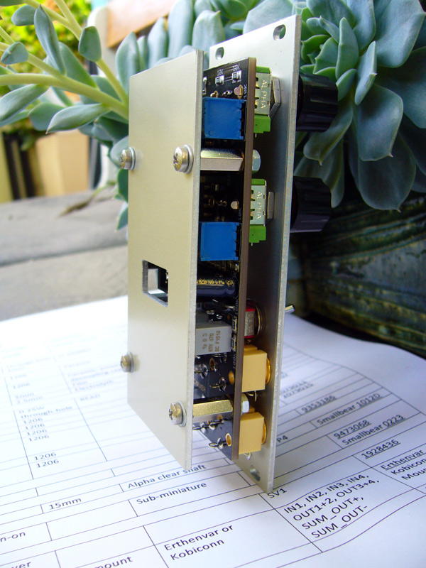
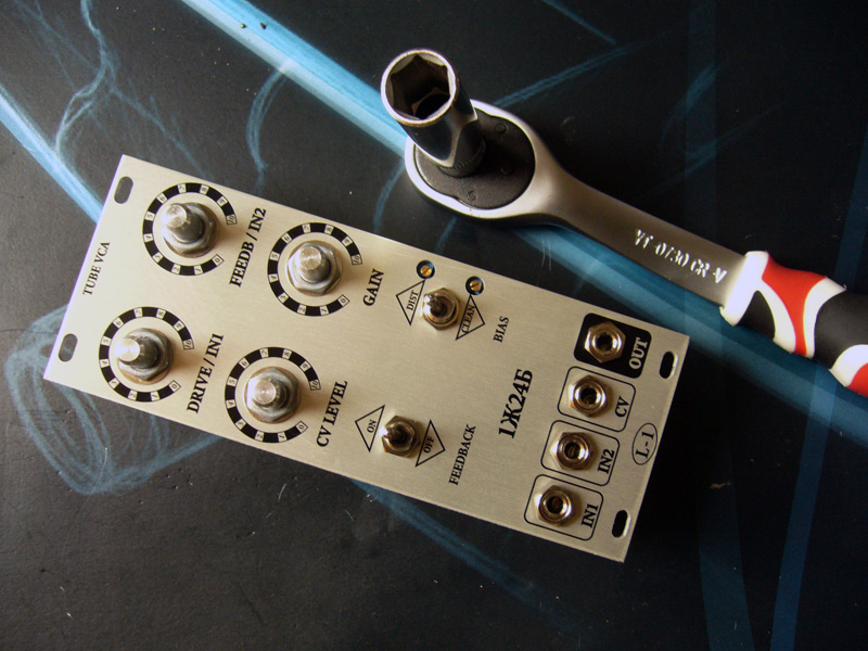
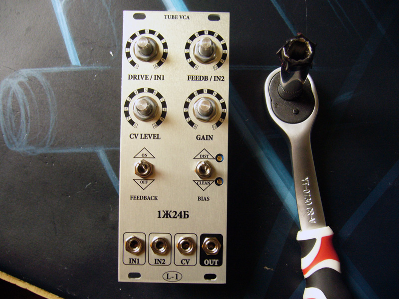
Panels:

Documents:
 Partlist.
 Front panel.
Assembling is pretty easy. Everyone can do it in a couple of hours.
Solder through-hole parts from low to high. First 10R resistors and diodes.
Then IC sockets.
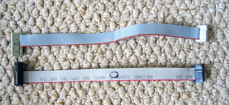
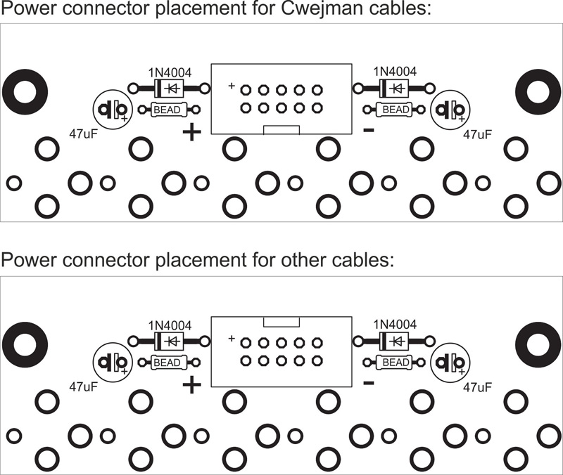
Important issue about power cables. I used Cwejman cable (white on the photo) which made upside down comparing to other manufacturers.
As it turned out, Cwejman is the only manufacturer making this way. Check your cable before soldering power connector.
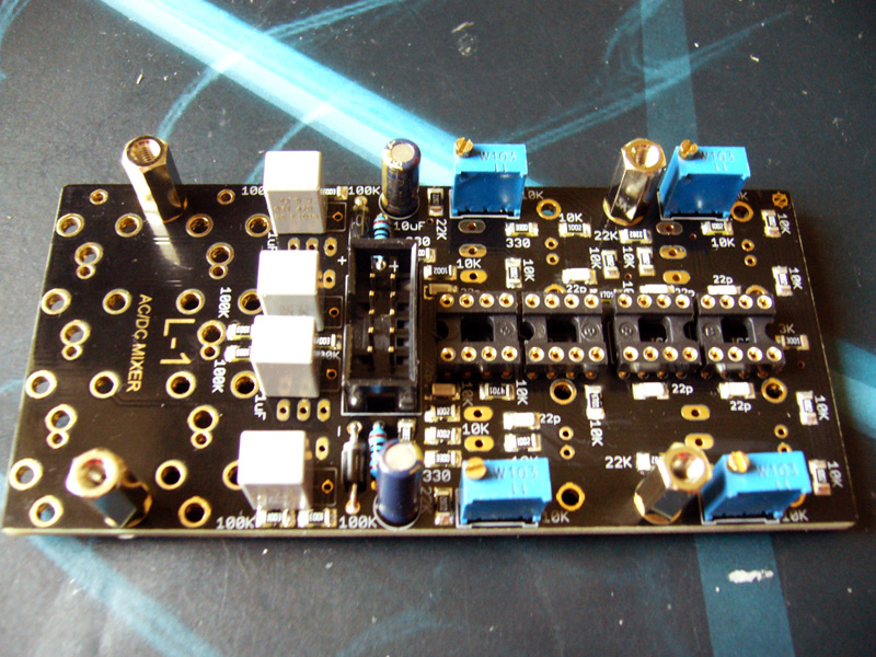
Then caps, power socket and trimpots. From low to high.
Now clean bottom side. Look how clean it is obtained.
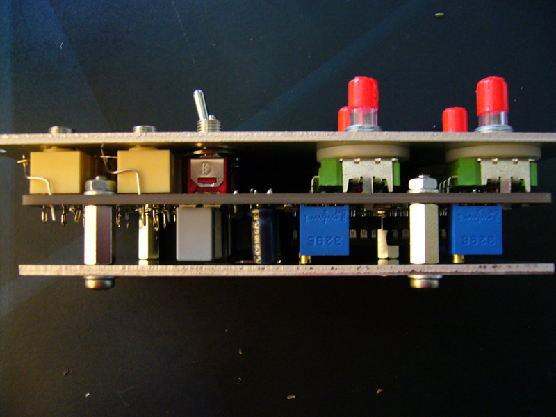
Mount spacers.
3. Mounting hardware.
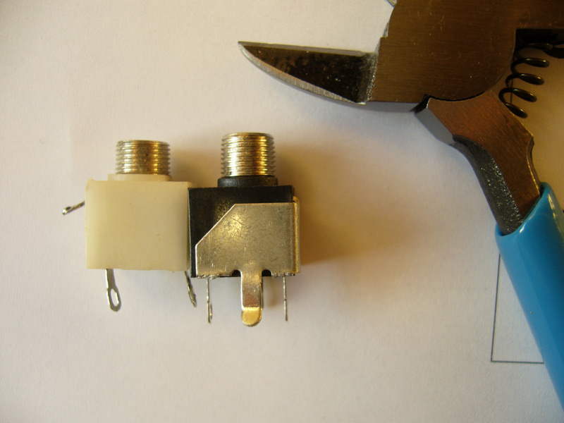
Erthenvar jacks are too high in comparison to Kobicon. Cut these legs with pliers. We need to achieve 10mm between board and panel.
Kobiconn jacks need ground leg soldering. I use cutted resistor legs.

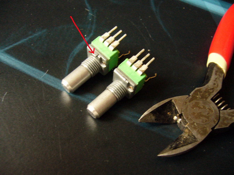
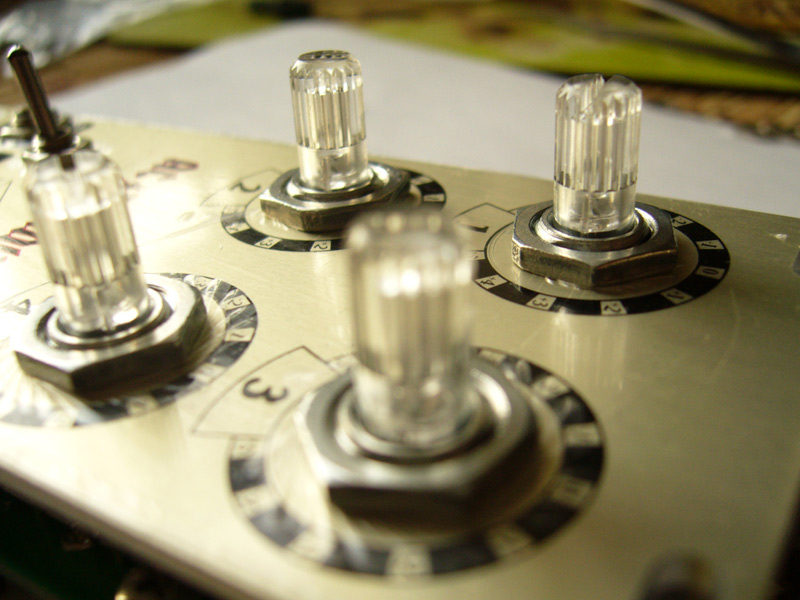
These spikes on pots need to be cuted.
Fit LEDs into pots.

If tight, cut skirt.
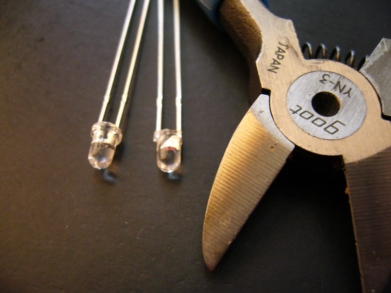
Insert LEDs.
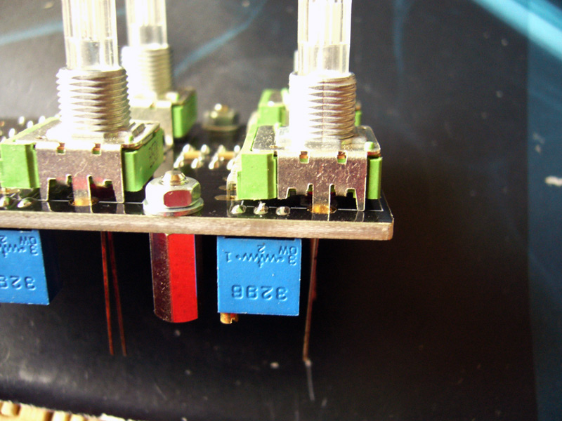
These legs of top two potentiometers need to be cutted to don't contact with solder joint. Sorry for this.
Now insert all hardware but don't solder.
I use thin washers with Kobiconn jacks to achieve 10mm.
Another way - nylon washers for pots and nothing for jacks.
Now place a panel. Don't overtighten a nuts, just by hand.
Check everything is exactly precise.
Adjust LEDs.
Now solder. Be accurate, hard to clean now if to make dirty.
Now tight a nuts, not strong just a bit. Pots have a washers, so screwdriver doesn't scratch a panel.
Switches and jacks haven't washers, so some protection is needed, I use insulating tape.
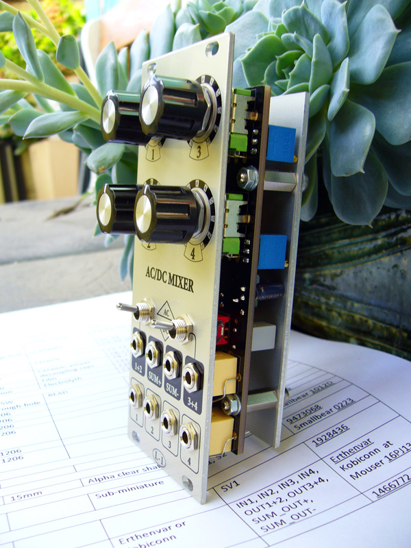
Ready. Very nice and precise.
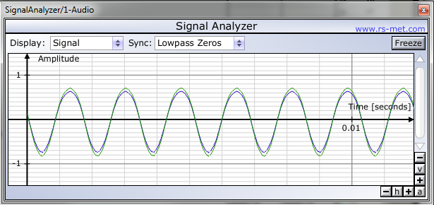
TRIMMING
Split 1 kHz sine wave into two. Connect one channel of analyzer to one wave. Second wave connect to IN1 of Mixer. Sum out connect to second channel of analyzer. Level pot turn to 0 (center).
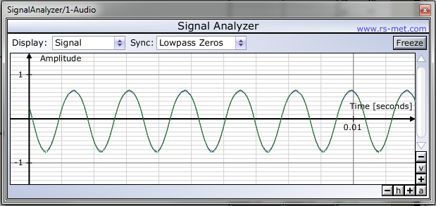
Our waves have little different amplitudes. Trim assotiated trimpot to make them equal.
Free download of Signal Analyzer here http://www.rs-met.com/software/freebies/SignalAnalyzer.zip
Ready. Repeat for all channels.
Now mount backpanel. Device is ready. Works and looks great!
(c) 2012 L-1 Synhesizer. E-mail: aleksei1laman@gmail.com